Graepel Italiana SpA |
||||||||||||||||||||||||||||||||||||||||||||||||||||||||
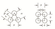
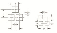
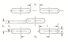
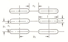
Perforated sheets - Technical features Shape of holes The most simple shapes are: round, square and triangular (equilateral). While the triangular hole is rarely used for specific purposes, round and square holes are indubitably the most requested types. Slot holes and rectangular holes (sharp edges) derive from round and square holes.
Besides these shapes, many others are available:
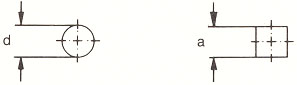
The latters find their major use for specific purposes, while the ones on the top of the page coincide with more than 80% of the overall production, and are used in several fields. The perimeter of the hole is not always required to be on the same level of the surface of the metal plate. Sometimes the whole contour of the hole is deformed upwards or downwards (countersunk or indented hole). While usually the holes on a metal sheet are deformed in the same direction, Graepel developed a system to combine the two directions of the deformings on unique metal sheet. Hole measurements and dimensions Round holes are determined by the measure of its diameter "d"; square holes are determined by the measure of the side "a". Diameters and sides up to 120 mm are possible.
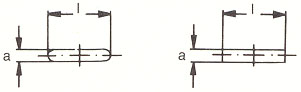
Slot and rectangular holes can be determined from the measures of their width "a" and length "l". The maximum dimension of "a" is 120 mm and "l" 200 mm or more.
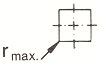
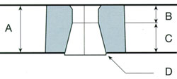
Holes obtained by punching are divided into three areas: on top the warping area, then the cut area, and lastly the breaking point area. The measure of the hole is obtained in the cut area. During the standard punching of a perforated metal sheet, the section of the holes is slightly conic in the breaking point area. It is important that the ratio between bridge "n" and thickness of the metal sheet do not go below 1, otherwise the space between the holes may break.
Pitch and bar Pitch correspond to the distance between the centres of two contiguous holes. Bar indicates the lesser unperforated area between two contiguous holes.
Perforated areas: beginings and ends Perforated areas are measured between the circumferences (outer sides) of the holes starting from the first to the last row of holes. Due to tooling reasons, the distance among punches is double or triple if compared to the perforation pitch. Therefore the complete perforation scheme can be obtained in full just after the second or third hit. Likewise, the end of a perforated area looks rough. This kind of beginning of perforation is called "double" or "triple initial gap". Thanks to the newest CNC punching presses, it is almost always possible to remove these initial gaps, but it is fundamental to know that since the original inquiry. Nowadays many modern toolings take advantage of the double feeding to minimize production timings and costs. Unfortunately not every tooling is able to obtain regular perforation beginnings and ends. Customers often opt out this aesthetic requirement in order to keep costs down. The double or triple initial gap system works with every kind of perforation.
Edges, unperforated areas and their measurement One of the most important benefits of perforated metal plates is the possibility to get edges and unperforated areas. Usually, the two long sides of perforated metal sheets up to 4 mm thickness have small unperforated edges, while the two short sides do not have any edges. Starting from 5 mm thickness the standards provide for full unperforated perimetral edges. Unperforated edges can be removed thanks to shear cutting. It is also possible to allow unperforated areas in different positions, and especially with sectional presses it is possible to satisfy almost every request about shape and position of unperforated areas. Edges must be measured starting from their limit on the outer side of the metal sheet, and not starting from the centre of the hole.
Cutting and shearing burr Just as in any other shearing system, perforation involves the formation of burr on the exit side of the punch. The amount of burr depends on various factors (type of material, tool grinding, clearance between punch and matrix, etc.). You must always consider that on the whole perimeter of the metal sheet cutting burrs (made during shearing) are present. These burrs are often facing opposite each other and the perforation burr. Important: unless otherwise agreed, the entering side of punches is shown on technical drawings. Open area The ratio between empty and full spaces, which is easy to determine thanks to the after-written formulas, is expressed as the percentage of the total perforated surface, threrefore it does not consider edges and unperforated areas. Flattening of perforated metal sheets Perforation causes tensions to the metal plate, deforming it; then it is necessary to flatten it with suitable muli-cylindrical flattening machines. For large metal sheets, wide unperforated surfaces, broad/irregular edges, materials which are very hard or with "difficult" perforated areas, tension may be so strong to impair the flattening process. Metal coils perforated then wrapped do not undergo any flattening, therefore flatness can not be guaranteed. Enquiries and orders When placing enquiries or orders, the following data must be sent: - quantity of sheets - quality of the raw material - thickness, width and lenght of the metal sheets - measurements of the hole (placement, parallelism for slot and rectangular holes) - pitch (if not indicated, the normal pitch will be used) - edges and/or unperforated areas - requested delivery terms When in doubt, please send a technical drawing, a sketch or a sample, if available. |
||||||||||||||||||||||||||||||||||||||||||||||||||||||||
| Graepel Italiana S.p.A 46018 SABBIONETA (MN) - Via Fondi, 13 - ITALY - Tel. +39 0375 220101 - Fax +39 0375 220262 R.I. MN / C.F. / P.IVA 00500630207 - REA 135337 - Cod. Mecc. MN005636 - Cap. Soc 516.450 i.v. - info@graepel.it |
||||||||||||||||||||||||||||||||||||||||||||||||||||||||